Bridge design
Material tests
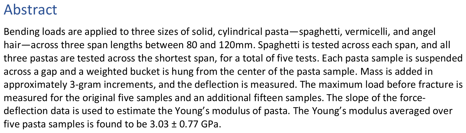
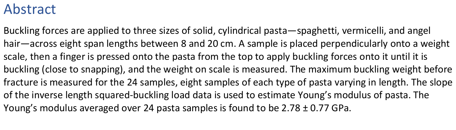
Testing the properties of different pasta types showed me the importance of basing engineering designs on scientific data. Bending tests measured how pasta spans deflected under added weight, giving an estimate of stiffness. Compressing strands of different lengths showed how length and thickness affected buckling loads. Pulling samples to failure, then comparing their diameters and breaking loads, provided an estimate of tensile strength. Click an abstract to read the full lab report.
Lab to design
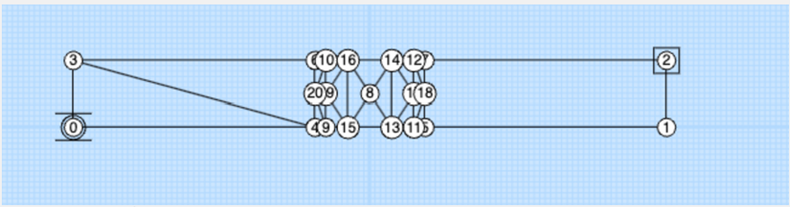

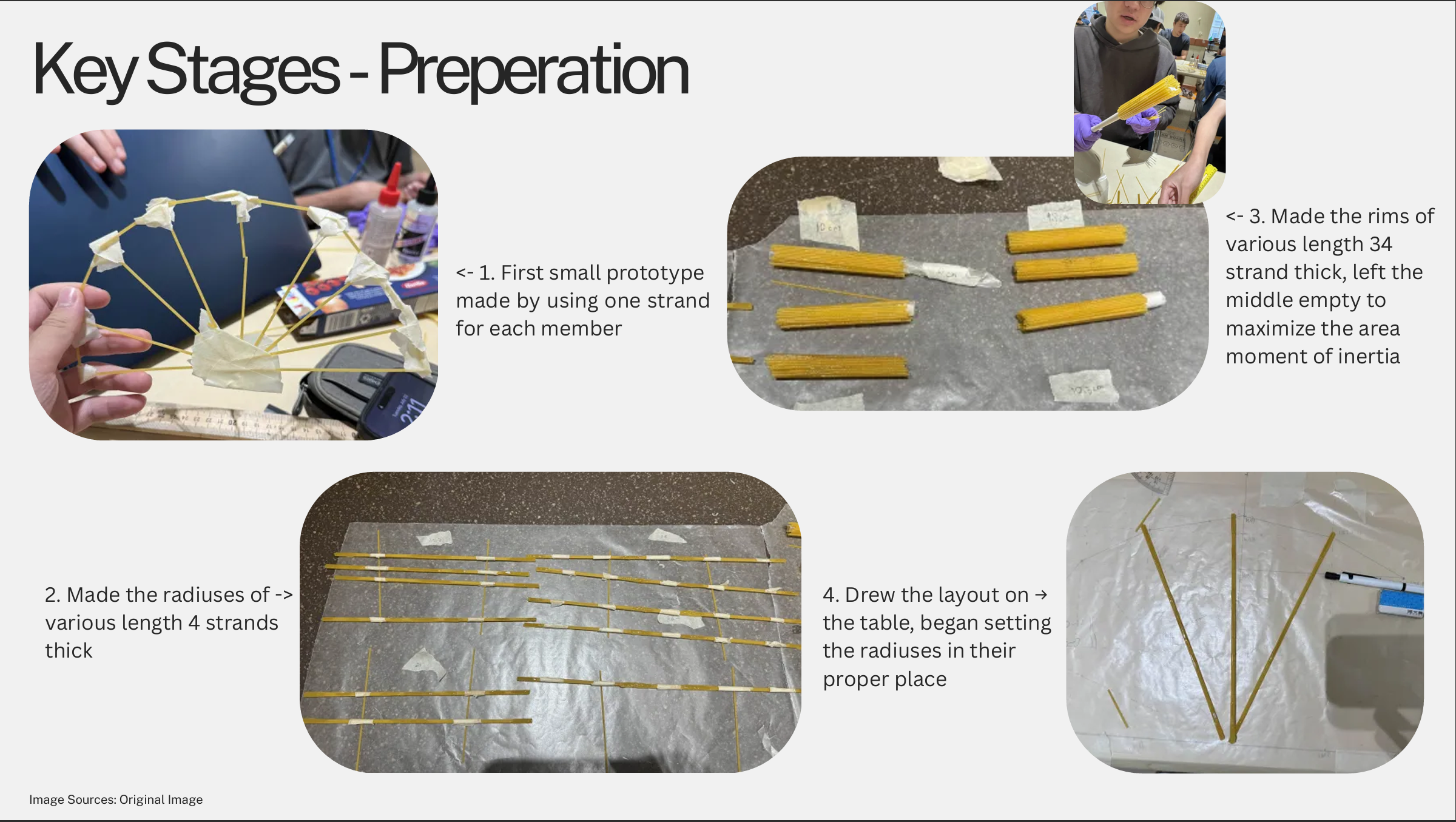
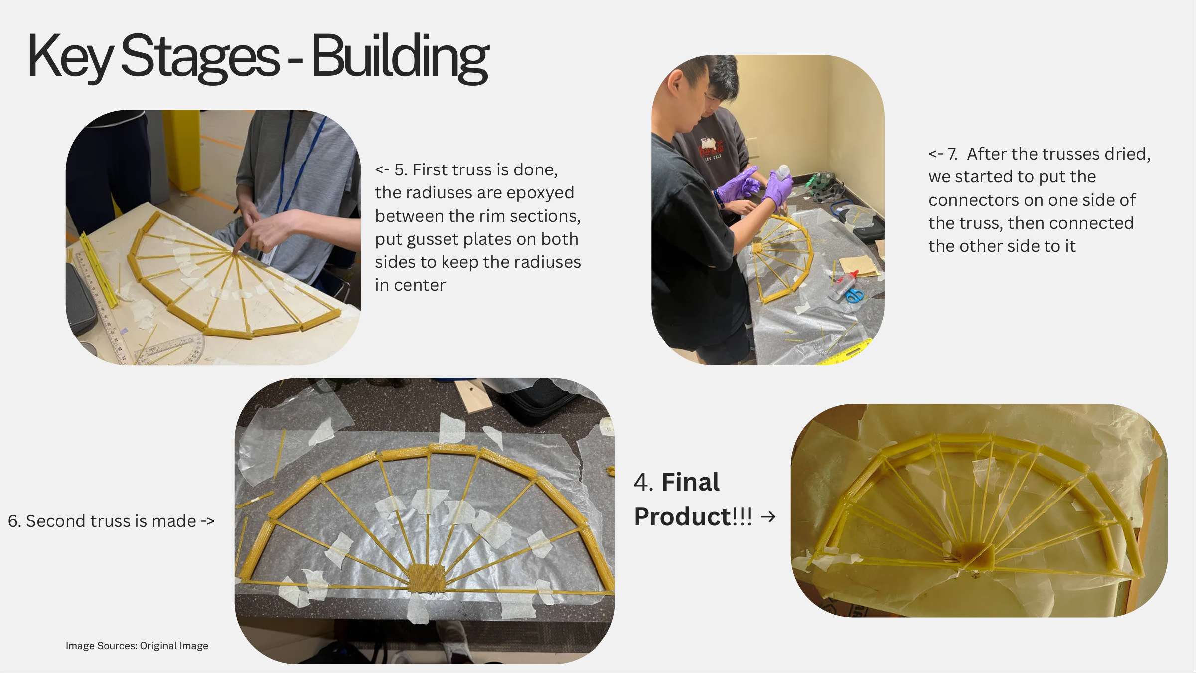
After measuring the material properties of different pasta types, we started developing our bridge design. We calculated the tension and compression forces in each bridge member and used the mass and load analyses to develop our final design. The truss model and method of joints helped identify members in tension and compression. Resolving forces into horizontal and vertical components made it possible to analyze a sample joint using static equilibrium. Comparing the material test results with the forces in each member helped us choose strand counts within the bridge’s mass allowance. Click a design image to view the full presentation.
Design to reality
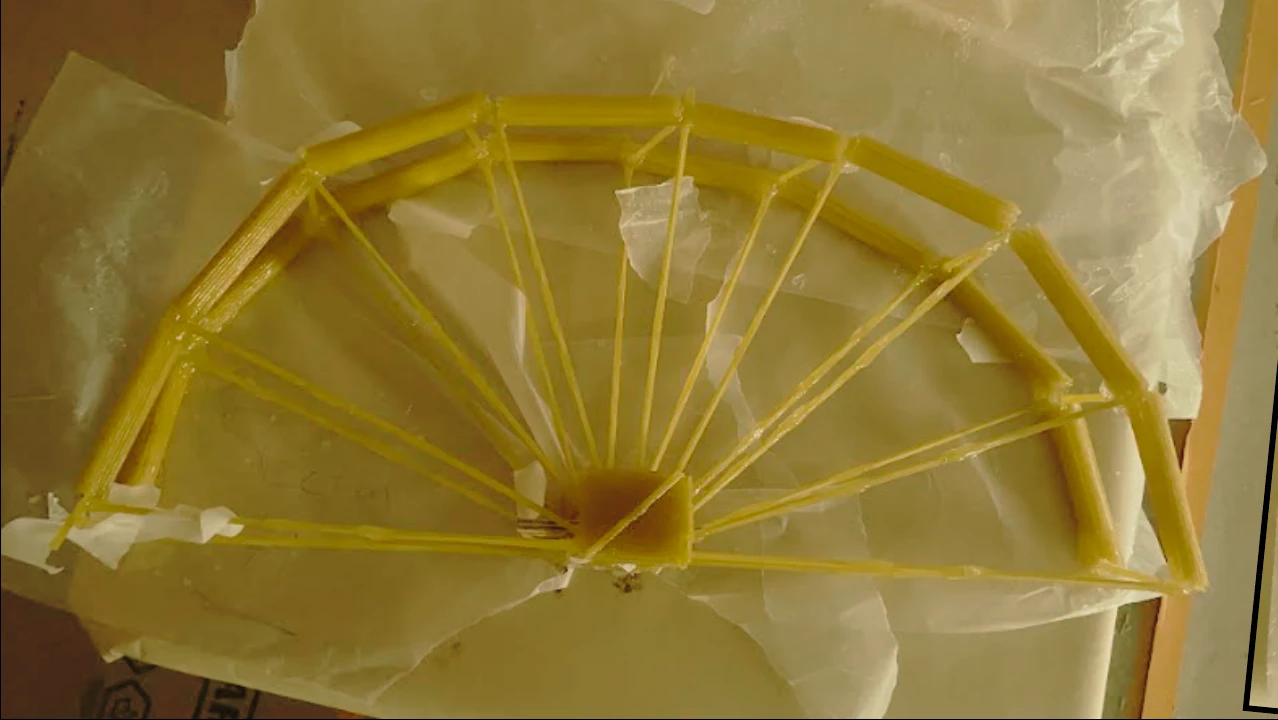
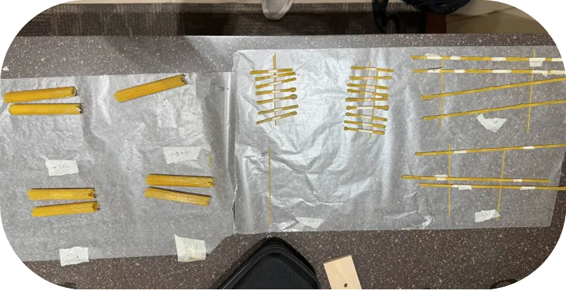
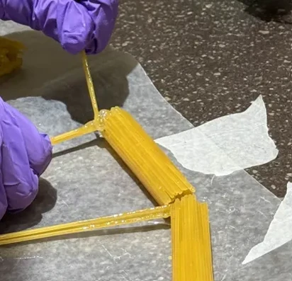
We chose hollow, 34-strand rims to resist buckling, with four-strand diagonals based on our force calculations. Forming the hollow sections proved difficult. Curved surfaces weakened epoxy joints, and uneven connector lengths prevented some joints from connecting properly. The heavy rim also strained the thinner supports. In a future build, we would use a lighter solid rim, reinforce the diagonals, and flatten or notch bonding surfaces. Simpler dimensions, standardized connector lengths, and earlier assembly trials would help us balance structural calculations with practical construction.